上一篇:Overview of variable resistors
下一篇:ON Semiconductor launches seventh-generation IGBT smart power module with outstanding performance
A brief description of the definition and working principle of the clamp circuit
Post Date:2024-02-21,MICRON
A brief description of the definition and working principle of the clamp circuit
What is a clamp circuit?
In electronics, a clamp or clamping circuit is used to add a DC level to an AC signal. By using a clamp circuit, we can place the positive and negative peaks of the signal at the desired level. Due to the phenomenon of DC level shifting, the clamp circuit is called a level shifter. A simple clamp circuit consists of an energy storage device such as a capacitor (C), a resistor (RL), a diode and a DC voltage battery
Working principle of clamp circuit:
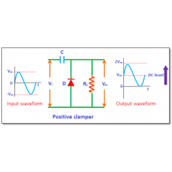
Clamp circuits subtract or add a DC component to the input signal. If a positive DC component is added to the input signal, the input signal will be pushed to the positive side, whereas if there is a negative DC component, the input signal will be pushed to the negative side. Therefore, we can identify two types of clamps by this phenomenon: positive clamps and negative clamps. If the clamp circuit moves the input signal upward, it is called a positive clamp circuit, as shown in the figure below .
Likewise, if the clamp circuit shifts the input signal downward, it becomes a negative clamp circuit, as shown in the figure below.
What is a clamp circuit?
In electronics, a clamp or clamping circuit is used to add a DC level to an AC signal. By using a clamp circuit, we can place the positive and negative peaks of the signal at the desired level. Due to the phenomenon of DC level shifting, the clamp circuit is called a level shifter. A simple clamp circuit consists of an energy storage device such as a capacitor (C), a resistor (RL), a diode and a DC voltage battery
Working principle of clamp circuit:
Clamp circuits subtract or add a DC component to the input signal. If a positive DC component is added to the input signal, the input signal will be pushed to the positive side, whereas if there is a negative DC component, the input signal will be pushed to the negative side. Therefore, we can identify two types of clamps by this phenomenon: positive clamps and negative clamps. If the clamp circuit moves the input signal upward, it is called a positive clamp circuit, as shown in the figure below .

Figure 1 positive clamper circuit diagram
Likewise, if the clamp circuit shifts the input signal downward, it becomes a negative clamp circuit, as shown in the figure below.
上一篇:Overview of variable resistors
下一篇:ON Semiconductor launches seventh-generation IGBT smart power module with outstanding performance